A subreddit dedicated to news, articles and general discussions related to the field of. Rules. The focal point of your post should be related to the subject of component-level electronic engineering as supported by the post tags / flairs below. Do not post about something just because it contains 'electronics'. Do not post questions on designing, repairing or troubleshooting electronic circuits (including questions on tools, equipment and parts sourcing) - these go in.
General discussions (specifications, use and purchasing advice etc.) about consumer electronics should go elsewhere. No commercial posts (advertising, selling, 'deals' or general product launch info on commercial/domestic electronic goods) - those go in. Add a flair/category tag to your posts (see 'Tags' section below) and please observe the additional posting guidance against the tags. Tags / Flairs Please categorize your post by clicking the ' (flair) button after submitting it.
Click a tag name below to view just the posts in that category Original discussion on an electronic engineering-related topic. Electronic engineering-related posts that don't fall into any other category.
An interesting electronics-related thing - a vintage item, circuit or part, or something newer with a novel design or implementation etc. Related to this subreddit. An electronic engineering-related news article or announcement. Show us your (or someone else's) circuit design and/or final build. A full write-up with design and construction notes would be much better than just pictures!
NB: This is for original work - pictures of stock kit builds will be deleted. A useful or insightful technical note on component selection, circuit design or testing etc. something beyond 'stick decoupling caps everywhere'! Related subreddits. digital circuit simulator. Programmable Logic Controllers. Electronic circuit design and repair questions go in.
View and contribute to ↓ (please edit!). You're getting a nice bright trace, your high voltage is fine.
No need to mess with the high voltage points. Everything you need to worry about should be under 300V, 260V is the highest my 2120 has apart from the HV to the tube.
Checking your power rails is one of the first steps of troubleshooting. If you have a supply problem then there can be all kinds of weirdness. I don't know how similar yours is, but on my 2120 the sweep circuit needs quite a few rails, the +5V, +/-12V and +24. You can isolate the sweep circuit from the CRT horizontal drive circuit.
Put the scope in X.Y mode and apply a voltage to the channel 1 input. In X.Y there is no sweep. The dot should move right or left depending on whether it is + or - and should not move vertically. If you center the dot and set the scope to 1V/div and apply -5V to the input the dot should move all the way to the left without moving vertically, +5V will make it go right. If this all seems normal than the problem is in the sweep circuit, not the CRT horizontal drive.
If the dot moves vertically at all on channel 1 then it is a CRT horizontal drive problem. You can repeat the same test on channel 2, however the dot should move vertically. If there is no movement then that channel is dead. The channel 2 problem was likely operator error, might have blown the vertical amplifier circuit on that channel. Likely not that big of a deal. Hard to say about the sweep problem.
Could just be aging components like capacitors. I don't know how different the sweep circuit is on the 2160, my 2120 doesn't have the delayed time base. It is worth keeping around if you do get another scope, having a working one is really helpful for repairing a broken one. You learn a lot by repairing them, you learn how they work and a lot about troubleshooting in general.
So far I have 3 that I have repaired, a B&K Precision 2120 20Mhz 2 channel, a Tektronix 2221A 2 channel 100Mhz and a Hitachi V-1150 4 channel 150Mhz. I got them in that order, all cheap and worked my way up to having 2 pretty nice scopes for less than $100 invested. This is an awesome guide put out by Tektronix, but the principles apply to all analog oscilloscopes. If I lived near you I'd take it, I don't have one with that component tester.

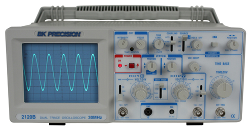
I bought a used BK Precision 2120B, but it arrived broken. The seller gave me a refund and I don't have to return it (shipping would probably make it not worth it anyways). So, I've got this on my hands and not sure what to do with it. From reading a bit, I gather that repairing an oscilloscope is pretty much out of the question for a beginner like me. I'm ok with that, but I've got it, and I've got this 'need' to do something with it. I don't need the money that I might get from selling it, and not particularly interested there. I am interested in learning more.
And I'm patient. So I can take my time with this. I don't watch TV, but I do watch a lot of informational videos on Youtube, so I'm open to recommendations on material there. My 'TV time' is pretty much 'educational time'. Be that Youtube, reading, or experimenting. Any recommendations on what a relative beginner should do with a broken oscilloscope?
A workshop manual,(sometimes called a 'technical manual') usually contains a schematic diagram,some description of the device's circuit operation,parts lists,troubleshooting information,etc. I think the B&K 2120B is known by other names as well,so somebody on this forum may just have the information on where you can get a manual,& an insight into the possible fault cause. Check through your existing 'User's Manual' to verify that you have all control settings correct.
This,as I said before,is to ensure that you are only chasing the real faults. My gut feeling with this problem, and the first avenue to exhaust, is that it is a settings or controls issue. Personally, I wouldn't even remove the case screws until I had familiarised myself with the operation of the scope. Do you have a probe connected?
I am not familiar with this scope but it must have a 'calibration' output connection/small pin/tiny loop. Whilst fiddling it would be useful to have the probe connected to that. The output is a square wave of maybe 1 volt, but it may not look much like a square wave due to other issues but at least it will be obvious that it is 'wiggling'.

My gut feeling with this problem, and the first avenue to exhaust, is that it is a settings or controls issue. Personally, I wouldn't even remove the case screws until I had familiarised myself with the operation of the scope. Do you have a probe connected? I am not familiar with this scope but it must have a 'calibration' output connection/small pin/tiny loop. Whilst fiddling it would be useful to have the probe connected to that. The output is a square wave of maybe 1 volt, but it may not look much like a square wave due to other issues but at least it will be obvious that it is 'wiggling'.
My gut feeling with this problem, and the first avenue to exhaust, is that it is a settings or controls issue. Personally, I wouldn't even remove the case screws until I had familiarised myself with the operation of the scope. Do you have a probe connected?
Kenwood 20 Mhz Oscilloscope
I am not familiar with this scope but it must have a 'calibration' output connection/small pin/tiny loop. Whilst fiddling it would be useful to have the probe connected to that. The output is a square wave of maybe 1 volt, but it may not look much like a square wave due to other issues but at least it will be obvious that it is 'wiggling'. Well, I managed to get 'something' after fiddling around for a while. The best I could manage is shown below with only the focus changed between the 2 pictures attached here. Time and volts are adjusted to make it as visible as possible with the maximum area.
I could not adjust it lower on the screen or further to the left. It is firmly in the upper-right corner with no ability to get it centered properly using the position, volt/div, or time/div dials.
The signal is a square wave from an Atari Punk Console. Well, I managed to get 'something' after fiddling around for a while. The best I could manage is shown below with only the focus changed between the 2 pictures attached here. Time and volts are adjusted to make it as visible as possible with the maximum area. I could not adjust it lower on the screen or further to the left. It is firmly in the upper-right corner with no ability to get it centered properly using the position, volt/div, or time/div dials. The signal is a square wave from an Atari Punk Console.
Something is surely amiss. With both Position controls set mid-way the waveform 'should' be close to the middle of the display.
So now the fun starts; you have to make the call as to passing this on to someone as a broken scope OR have a go at fixing it, possibly with forum guidance. As the 'B' series Service manual is not freely available, I'd suggest you upload the copy you have to a free manual repository so participants can download it and then we're all on the same page.
From the sticky in the Repair board: Here's a couple that many find popular: First steps are to check all the low voltage PSU rails are within spec. Study of CRO principles will guide your understanding of the blocks of circuitry used and how they deliver a waveform to the display: What we see in your pics is an imbalance in the CRT plate voltages, ie. The Position controls are set to extremes just to get the waveform on the display. Those CRT plates (horizontal & vertical) use electrostatic deflection of the electron beam and for the waveform to be in the middle of the display the voltages to the plates must be in balance.
This is a simplistic overview to hopefully point you in the right direction. Another doc that many find useful is this Tek troubleshooting guide: There are many of us here that can step you through this repair, you have another scope, no doubt a DMM and soldering iron too and if you want to go the distance you'll have another working scope.